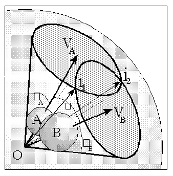
Figure 1
Shadow representation of the solid angle of two spheres A and B
Structural Chemistry Group, Department of Chemistry, University of the Witwatersrand, Private Bag 3, WITS 2050, Johannesburg, South Africa.
ABSTRACT
A new algorithm involving the calculation of the solid angle of a molecule about a point as a measure of steric size has been developed. The algorithm calculates the total solid angle in a step-wise fashion, summing all regions of individual atom solid angles and overlapped atoms, taking into account all orders of possible overlap of multiple atoms. The results for several molecular fragments have been compared to previous solid and cone angle calculations and improved correlations were observed.
INTRODUCTION
In 1977 the cone angle was introduced by Tolman for the quantification of the steric size of molecular fragments about a point, such as a ligand about a metal atom in a complex [1]. For radially symmetrical ligands like P(CH3)3, the cone angle is calculated simply as the vertex angle of a cone constructed with its apex at the site of interest, the metal atom in the case of ligands, and its sides tangentially touching the outermost atoms of the molecular fragment. This effectively approximates the ligand with a perfect cone. Clearly, however, this does not take into account the possibility that the ligand may have a shape far removed from that of a cone, with the gaps between separate sections of the ligand contributing to a lesser steric size than that estimated by the cone angle. Therefore, for many ligands and molecular substituents that are not near conical in shape, the Tolman cone angle is not likely to be that good a quantification of steric size about a point.
Several alternative techniques have been used in the study of steric interactions about a point. One of the most recent of these has been the use of solid angles [2,3]. The solid angle of a ligand about a point can be most easily visualized by imagining a point light source at the centre of the metal atom, or point of interest, creating a shadow of the ligand on a sphere centred at the light. The area of the shadow divided by the radius of the enveloping sphere gives the ligands solid angle in units of steradians. This can be seen in the schematic diagram of the solid angle of two spheres shown in Figure 1 .

Figure 1
Shadow representation of the solid angle of two spheres A and B
Solid angles of molecular fragments have been calculated in both a fully numerical way [2], as well as in a step-wise semi analytical way [3]. The latter approach has its advantage primarily in the speed of calculation. However, there are numerous complications involved in this approach and the algorithm published [3,4,5] to date has several drawbacks which make it unsuitable for molecules of large size. This is due to the fact that this algorithm assumes that the total solid angle is simply the sum of all pairs of overlappinga atoms, minus the solid angles of atoms that have been counted more than once. This procedure works only when not more than two atoms are overlapped at the same time. However it can be shown that even in a molecular fragment as small as CH3, regions of overlap of up to four atoms can occur (see below).
This solid angle algorithm has also been used in the calculation of solid angle radial profiles [4]. This involves construction of a sphere about the point of perspective and calculation of the solid angle of the intersection of this sphere and the atoms of the molecular fragment. The repetition of this calculation for a range of radii that cover the entire molecule yields the solid angle radial profile, which is useful for the determination of the radial dependence of the steric size of the molecular fragment. An important difference between this calculation and the total solid angle is that overlap can only occur between atoms that show physical overlap and not just angular overlap. This means that atoms which may show angular overlap in the total solid angle calculation, but which are at different distances from the apex, are likely not to have overlap at any radius of the profile calculation. This results in both the solid angle found at any radius being smaller than the total solid angle, and the likelihood of multiple overlap between more than two atoms being reduced. However multiple overlap may still occur and result in errors in the profiles calculated. The solution to the errors in both the total solid angle and the radial profile calculations clearly involves taking into account the solid angles of the regions of overlap of order higher than two. In other words the assumption that no more than two atoms can overlap as observed from a point perspective needs to be reassessed.
METHOD
The new algorithm presented here follows an approach similar to the original semi-analytical algorithm of White et al. [3]. However, in order to generalize the calculation of overlaps to orders greater than two, numerous modifications to the mathematics needed to be made.
The Solid Angle Measurement
The general equation for the solid angle of a region S on the surface of a sphere of radius r is given in equation 1:

where r is the vector from the centre of the sphere to a point on the surface, r is the length of that vector and d is the vector element of area at the surface. The integration is performed over the region of interest S, which can represent the shadow of the molecule described above. For single atoms the region S is simply a circle and equation 1 reduces to:

where is the semi-vertex angle of the enveloping cone.
However, when one wishes to solve the equation for the case of a region representing the overlap of two atoms, the full two dimensional integral cannot be solved analytically. By integrating over one angle, however, equation 1 can be written in a form similar to that of equation 2, but with the cos( ) term replaced by a one dimensional integral. The approach used in the original algorithm [3] involved projecting the two atoms onto a plane normal to a vector OG down the centre of a cone enveloping the two atoms. Figure 2 shows two choices for the vector OG, one with the enveloping cone touching the outer edges of both atoms, and the other with OG through the region of overlap, and the cone enlarged to envelope both atoms. The planes perpendicular to each choice of OG, onto which the projections are made, are described in more detail in Figures 3 a & b. Only the geometry described by the first choice, indicated as part a and G' in Figure 2 and detailed in Figure 3a was used in the original algorithm [3]. The solid angle was calculated by integrating the unshaded region in Figure 3a over the angle about the point G, along each ellipse with the integration limits at the ellipse intersection points. This approach of projecting ellipses onto a two dimensional plane has also been used in the analytical calculation of molecular surface areas [8]. In that calculation the circles of atomic intersection and great circles of the atoms concerned were found to form ellipses in orthogonal projection onto a plane. In this calculation here, however, the ellipses arise from non-orthogonal projection of spheres from a point perspective.
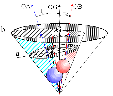
Figure 2
Projection of two atoms onto the plane perpendicular to vector OG:
a - OG defines smallest enveloping cone, used in White et al.[3]
b - OG constructed through region of overlap
The approach used in the new algorithm is to perform a similar projection, but to use the second choice of OG and integrate only the area of overlap, as shown in Figure 3 b, simplifying the calculation and removing the need for the segment correction described by White et al. [3].
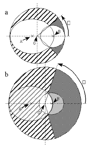
Figure 3
a - Ellipse projection used by White et al.
b - Ellipse projection with G in region of overlap
To understand the necessity of dealing with regions of overlap involving more than two atoms, ie. of overlap order higher than two, it is best to refer to a simple example. Figure 4a shows the projection of a hypothetical CH3 ligand with the atomic radii chosen so that only double overlap occurs, whereas in Figure 4 b the radii have been chosen such that even quadruple overlap occurs. If we follow the procedure of summing all single atom solid angles, followed by subtraction of all double atom overlap regions, the two situations result in individual sections of the projection being counted differently in the total solid angle:
a Summing all the single atom solid angles in Figure 4a results in each region of double overlap being counted twice. Subtraction of those regions once each results in the evaluation of the correct final solid angle. Each demarcated region is counted only once, as indicated by the number '1' in each region in Figure 4 a.
b Following the same procedure for Figure 4b results in all single atom regions as well as all double overlap regions being counted once only. However, the regions of triple overlap are not counted, and the solid angle of the region of quadruple overlap is effectively subtracted twice. Clearly this gives an erroneous result.
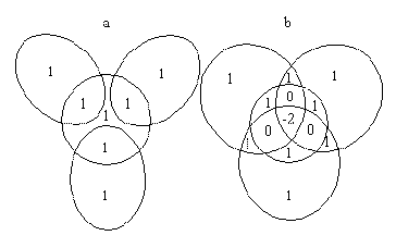
Figure 4
a - CH3 with only C-H overlap
b - CH3 with all pairs of atoms overlapping
In the earlier algorithm this problem was partially compensated for by a modification of the counting algorithm such that only a certain subset of double overlaps were taken into account. For most molecules that have their centre-most atoms defined first, for example CH3, this works quite well to reduce the error. However this approach is not general and does not remove the error, but merely compensates for it. For molecules in which high order overlap is prevalent, the calculation is still likely to yield large errors.
Clearly the solution is to take into account all higher orders of overlap. A procedure to achieve this can be demonstrated by the example of the multiply overlapped CH3 molecular fragment for which the projection is shown in Figure 5 :
a Firstly all single atom solid angles are summed. This counts regions of single overlap only once, regions of double overlap twice, regions of triple overlap three times, and the remaining region of quadruple overlap four times.
b Subtraction of all regions of double overlap once will correct those regions but result in all triple overlap regions being counted zero times and the quadruple overlap regions being counted minus two times, as was also the case in Figure 4 b.
c Addition of all the triple overlap regions corrects for these regions, but leaves the quadruple overlap region being counted twice.
d Finally a subtraction of one quadruple overlap region results in the evaluation of the correct total solid angle with all regions being counted once only.
The general procedure then is to add all single atom solid angles, subtract all double overlap regions, add all triple overlap regions, subtract all quadruple overlap regions, add all quintuple overlap regions and so on until the highest order of overlap present in the molecular fragment has been taken into account. This is general for all orders of overlap and will result in the correct total solid angle for the molecular fragment concerned.
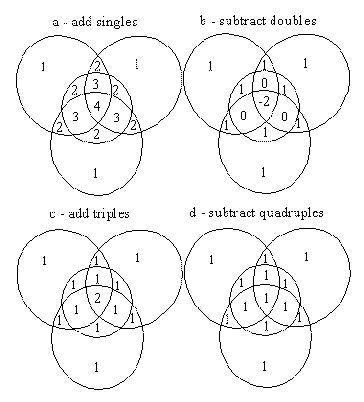
Figure 5
CH3 with successive addition and subtraction of regions of overlap
This alternating pattern that arises as one looks at progressively higher orders of overlap has also been observed in molecular surface area calculations [8].
The Multiple Overlap Algorithm
For the sake of computational simplicity, the origin O={0.0,0.0,0.0} is taken as the point of perspective from which the solid angle is calculated. It is a trivial procedure to translate any molecular data to positions that satisfy this requirement for the required point of perspective. Any atom Aib can be described by the vector vi to the centre of the atom, and its radius ri. For the purpose of both solid and cone angle calculations, however, it is more convenient to use the semi-vertex angle i instead of ri , where i is given by i = arcsin(ri /vi). The semi-vertex angle is the angle between the vector vi and the cone about vi that envelopes the atom and has its apex at the origin. A schematic representation of this can be seen in figure 1 where A and B are the semi-vertex angles of the two atoms A and B respectively.
Therefore, for solid and cone angle calculations about a point perspective, atoms are uniquely equivalent to their enveloping cones. In order to consider regions of atomic overlap, we therefore need only concern ourselves with the interactions of a set of cones, all with a common apex at the origin. The vectors iij to the intercepts of any two atoms Ai and Aj lie along the lines of intersection of the relevant cones. This was described in Figure 1 where the atoms A and B had the two intercept vectors i1 and i2. In order to perform the final integration of the solid angle of a particular region of overlap of order m
1, it is necessary to determine the vector G that lies within the overlap region. All intersection vectors iij and the vector G are calculated as unit vectors because only their direction is of importance.
The complete computational algorithm can be described in two sections:
A The counting algorithm involves the determination of the particular combination of individual regions, including all multiple overlap regions that comprise the total solid angle, and the details of those regions. These details include the parameters for the atoms concerned and the relevant intercept vectors between those atoms.
B The calculation of the solid angle of a given region of arbitrary order of overlap from the parameters vi, i and ii for that region.
Section A turns out to be considerably more complicated than B and shall be dealt with first.
Counting Algorithm
In order to optimize the speed at which the regions contributing to the solid angle were found from all possible permutations present in any molecular fragment, use was made of some important observations:
i) For any set of m atoms, mth order overlap can only occur if all m possible subsets of m-1 atoms have regions of (m-1)th order of overlap. For example, the quadruple overlap region C-H1-H2-H3 in Figures 4 and 5 occurred together with all four triple overlap regions (3 C-H-H regions and 1 H-H-H region). By inspection, it can be seen that if just one of the triple overlap regions did not occur, then the quadruple overlap region would also not occur. This is true for all orders of overlap.
ii) For any region of overlap of order m, the set of vectors iij,m can be found from the m sets of iij,(m-1) intersection vectors, or, alternatively, from the set of two atom intercepts which contain all intercepts that occur in the particular molecule. This means that the vectors iij for all intercepts that ever occur need only be determined once for each two atom intercept Ai:Aj. All higher order overlap calculations then simply obtain their intercept vectors from this set.
The algorithm itself involves the following basic procedure:
a) Omission of all fully overlapped atoms since they are effectively in the shadow of the rest of the molecule and do not contribute to the solid angle.
b) Summation of all single atom solid angles
c) Subtraction of all double atom overlap regions. All possible combinations of two atoms are tested for overlap using the condition: ij < ai + aj => overlap ij > 0, where ij is the angle between vi and vj as can be seen in Figure 1 . For each successful case the intercept vectors iij are calculated using the intercept equations in the appendix. The vector G is calculated as the average of the two intercept vectors, and the solid angle for each region of m=2 overlap is then calculated.
d) Determination of all higher order regions of overlap. If m is odd, the solid angles are added to the total solid angle, whereas if m is even, the solid angles are subtracted. For each order of overlap, all possible combinations of m already considered regions of (m-1)th order overlap (Oi, i {1,m})c are tested. Clearly, for any mth order overlap to exist, m regions of (m-1)th order overlap Oi must also exist. For each combination of m Oi's, several conditions must be met for overlap to be present:
i) Only m different atoms (Ai, i {1,m}) may be present in all Oi's together.
ii) Each atom must occur exactly m-1 times, one occurrence per overlap region for m-1 of the m separate regions. This also means that for each atom there must also be a unique (m-1)th order region of overlap in which that atom does not occur.
iii) For each combination of one atom Ai and the (m-1)th order region Oi in which it does not occur, there must be angular overlap between Ai and Oi.
In the process of testing for condition ii), the set of m atoms and the set of m regions of (m-1)th order overlap are ordered so that each atom Ai is associated with one overlap region Oi, which does not involve that atom. This facilitates the testing of condition iii), which involves going through all intersection vectors involved in the particular Oi overlap region and testing whether
they lie within the cone of Ai.
This procedure for finding regions of multiple overlap is not trivial and a simpler approach involving searching all permutations of m single atoms for mth order overlap can be envisaged [7]. However, it was felt that use of the above conditions would markedly improve the speed of the entire calculation.
From the above testing procedure several different cases of overlap may occur. These have been described schematically in figure 6:
a) Oi is fully enveloped by the cone of Ai. The solid angle for the mth order overlap region is then taken directly from the value already calculated for Oi, and no further calculation is required for the particular combination of overlaps. The number of ellipses comprising the region of overlap is less than the order of overlap (n<m). The example given in Figure 6a involves quadruple overlap generated by the overlap of an atom Ai with a triple overlap region Oi. In this case it can be seen that the quadruple overlap is equal to the triple overlap Oi. The number of bounding ellipses to this region, 3, is less than the order of overlap, 4.
b) The resulting region of overlap has more than m intersection vectors, four of which involve the same atom (n
m). In this case the vector G is placed at the centre of that atom so that its contribution to the solid angle can be calculated using a modification of equation 2d. The example in Figure 6 b involves a region of triple overlap where the three atoms are arranged so that one atom, Ai, bounds the region of overlap in two places. Here the number of bounding ellipses is 4, which is greater than the order of overlap, 3. Placing G on the vector vi results in the two ellipses due to Ai being described by circles on the projection plane, simplifying the calculation.
c) The overlap region has m intersection vectors and involves m atoms (n=m). In this case G is calculated simply as the average of all the intersection vectors, ensuring that it lies well within the region of overlap. For computational convenience, if G is found to be particularly close to one of the atomic vectors vi, then G is made equal to the unit vector i. This allows the contribution that atom makes to the solid angle to be calculated in the same way as in the previous case. Figure 6c describes the case for triple overlap where three atoms overlap so that each contributes one of the three bounding ellipses.
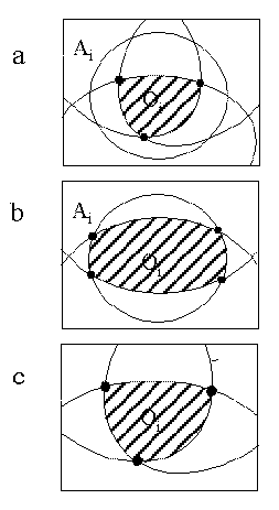
Figure 6
Types of Overlap Regions:
a - Overlap enclosed by single atom
b - Single atom forms more than one segment
c - Normal Overlap Region
Although it is possible to conceive of many other possible cases for a region of overlap of a particular order, the removal of all fully overlapped atoms from the calculation at the first stage effectively removes all but the three distinct cases above.
For each region bounded by n ellipses, the ellipses are dealt with individually.
Integration of arbitrary region
Single atom solid angles are simply calculated using equation 2. Regions of overlap, however, require more detailed calculation. In the original semi-analytical algorithm [3], the double overlap integration was achieved by projecting the single atom cones onto a plane normal to the vector G and at unit distance from the origin, where G was calculated as the vector down the centre of the cone that enveloped both atoms (figure 2 and 3a). The atoms were found to be represented by ellipses on the plane. Calculation of the intercepts between the ellipses yielded the angles of intercept on the plane.
In the new algorithm, G is placed within the region of overlap by calculating the vector OG as the average of the intercept vectors bounding that region. For double overlap this is described in Figures 2 and 3b. For triple overlap refer to Figures 6 c and 7. Having G within the region of overlap simplifies the computation considerably. The parameters of the ellipses, and hence the values of the ellipse intercepts, depend on the position of G. The angles of intercept are clearly different in Figures 3 a and 3b. For each region of overlap consisting of n individual segments we have n intercept vectors, with each segment bounded by two intercept vectors. For example the region of triple overlap described by the dotted region in figure 7 is bounded by three ellipses, each being the projection of one of the atoms. Each ellipse can be dealt with separately, as shown by the shaded region in Figure 7 , and has the angular limits 1 and 2 presented by the relevant two of the three intersection vectors. The ranges are determined by rotating all vectors such that OG = {0.0,0.0,1.0}, and then setting all values of z to zero. From the resulting projection of the intercept vectors onto the xy plane (vectors I1 and I2), the angles between the interceptse and the vectors to the atom centres can readily be calculated without any need for the calculation of the actual (x,y) positions of the intercepts.
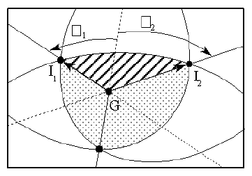
Figure 7
Region of triple overlap projected onto the plane perpendicular to G
If the intercept vectors had not been calculated, an alternative approach to the calculation of the intercept angles would be to calculate the (x,y) positions of the intercepts between the individual ellipses on the plane [7].
In the actual calculation of the solid angle presented by each ellipse (shaded region in Figure 7 ), all that is required are the angles 1 and 2 and a description of the ellipse with its semi-major axis along the x axis. Each ellipse is calculated independently and is described by the following ellipse equation:

where the parameters a, b and c are the semi-major axis, the semi-minor axis and the shift from the origin along the major axis, respectively. These parameters are dependant on i and the angle i between the vector OG and the vector vi for each atom (see Figure 2 ), and are calculated using equations simplified from those used in the original algorithm [3]f. The simplification used is simply that no account is taken of whether the ellipse is to the right or the left of the origin. Since this is only reflected in the sign of c, it can be introduced before the integration of the ellipse. This is possible because the sign of c was already determined during the counting algorithm stage by comparing i to the angle between OG and the intercept vectors.
The actual calculation of the solid angle is then achieved by integrating each of the ellipses over their respective ranges. The actual parameter integrated in each case is given by equation 4 [3]:
![0UPSILON SUB n~ = ~ LEFT[ {~1~+~LEFT({sigma SUB n.LEFT({c SUB
n }OVER{{a SUB n}^2}~cos phi RIGHT)~+~ sqrt{LEFT ({{c SUB n
}^2 ~cos ^2 phi}OVER{{a SUB n}^2}RIGHT)~+~LEFT({cos ^ 2 phi} OVER
{a SUB n}^2~+~{sin ^ 2 phi}OVER{b SUB n}^2 RIGHT).LEFT(1~~{{c
SUB n}^2}OVER{{a SUB n}^2} RIGHT )}} OVER LEFT({{cos ^2 phi} OVER
{a SUB n}^2~+~{sin ^2 phi}OVER{b SUB n}^2 }RIGHT ) RIGHT)^2~}RIGHT]^{~~-1
OVER 2}](../equations/small_multieq4.gif)
where an, bn and cn are the ellipse coefficients for ellipse n, and n is the sign of the c shift. The parameter m is integrated over from - 1 to 2.
The final solid angle for the kth region of mth order overlap comprising n ellipses is given byg:

Calculation of the total solid angle
mk is the solid angle of a particular region of multiple overlap, and consequently forms only a part of the total solid angle as calculated according to equation 6, which represents the counting algorithm:
![0OMEGA SUB {(total)}~ =~ SUM FROM {m=1} TO M [~ SUM FROM {k=1}
TO K (~(-1)SUP {m+1}TIMES OMEGA SUB {mk}~)~ ]](../equations/small_multieq6.gif)
Again the symbol m is the order of overlap being considered and M is the maximum order of overlap possible, which cannot be greater than the number of atoms present. For each order of overlap m there are K possible regions of overlap to be taken into account and each is symbolized by k. The fact that all regions of odd order of overlap are added, while those of even order are subtracted is incorporated into the (-1)m+1 part of the equation.
RESULTS
The determination of the solid angle (total) of an example CH3 molecule (figures 4b and 5(a-d)) was performed in three comparative calculations:
Method A The calculation of the solid angle by the summation of all pairs of overlapped atoms, followed by the subtraction of all over counted single atoms.
Method B The calculation of the solid angle by the summation of select pairs of overlapped atoms, followed by the subtraction of all over counted single atoms. This is the procedure used in the original algorithm [3].
Method C The calculation of the solid angle by the procedure described in this paper, in which all instances of multiple overlap are taken into account.
The results for these calculations are summarized in Tables I, II and III for methods A, B and C respectively.
A comparison of the results of the calculations using methods A and C shows that overlaps of order greater than two need to be considered in the semi-analytical approach to the calculation of molecular solid angles. As expected, both methods yielded the same answer after the subtraction of double overlaps. In method C, however, the further addition of the missing triple overlaps and subtraction of the quadruple overlap then gives a markedly different final answer. It is interesting to note that the quadruple overlap calculated is identical to the triple overlap (H1-H2-H3). This is expected since the particular triple overlap region is fully overlapped by the C atom, and so is identical to the region of quadruple overlap. Compare Figures 4 b and 5 to Figure 6 a.
The selective permutation algorithm employed in the original procedure (method B) shows considerably better agreement with the full multiple overlap algorithm (method C). However there is still a difference in the results, and this difference need not always be small. This can be demonstrated by the following comparison of values for several molecular fragments shown in Table IV and Figure 8 .
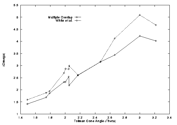
Figure 8
White et al. and Multiple Overlap solid angles versus the Tolman cone angle
Both solid angle measurements give an approximately linear relationship with the cone angle measurements. The multiple overlap calculation deviated least with R=0.984 as opposed to the 0.963 for the double overlap calculation. In both cases the intercept with the y axis was not zero, but again the multiple overlap fitted better with -1.10 as compared to -1.44 for the double overlap calculation. Both fits had slopes greater than one, with the multiple overlap at 1.69 and the double overlap at 2.02.
A comparison of solid angle radial profiles [4] determined by the different methods B [3] and C has been performed for the ligand PPh2Me. In Figure 9 it can be seen that the two profiles fit quite closely. This is due to the fact that, as described before, regions of multiple overlap are likely to be far less prevalent in the radial profile than in the total solid angle. The deviations in the maximum solid angle as well as the radial position of the maximum are small and can be attributed to the corrections introduced by the new algorithm. A further improvement is demonstrated by the increased smoothness of the profile for the multiple overlap algorithm.
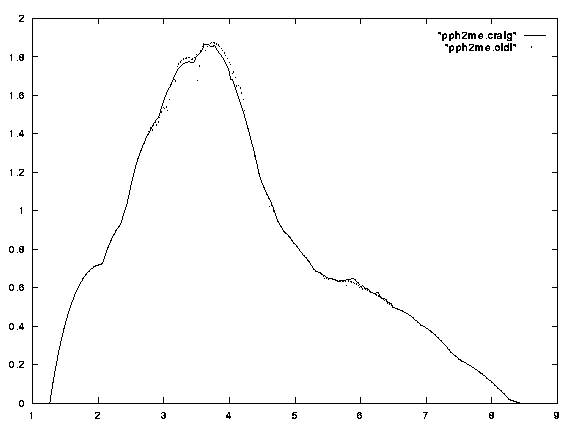
Figure 9
Solid angle radial profile of PPh2Me
CONCLUSION
An improved algorithm to determine the solid angle of molecular fragments about a point perspective as a measure of steric size has been developed. It has been shown to be more accurate and general than the previous semi-analytical solid angle steric calculation on which it was based [3]. It has also been shown to work well in extended steric calculations such as the radial profile [4]. Since the procedure involves the use of a general calculation based solely on the modelling of atoms as spheres about a point perspective, it can be used in the calculation of various steric effects about a point, including steric effects in ligands about a metal atom, and steric effects about reaction sites. It is also possible to use the algorithm for the calculation of the average solid angle of a set of conformers generated from molecular mechanics calculations [5].
ACKNOWLEDGEMENTS
The author would like to thank David White for the provision of the molecular data used in the original semi-analytical algorithm [3], Ryan Lemmer and Jeremy Smith for help in the testing of the algorithm, Neil Coville for help with proof reading and the Structural Chemistry Group at the University of the Witwatersrand for the use of their computing facilities.
APPENDIX
The intercept equations
The vectors to the atomic intercepts were calculated according to the following set of equations:


The vectors i1 = (i1x,i1y,i1z) and i2 = (i2x,i2y,i2z) are normalized and indicate the angular direction from the origin along the lines of intercept of the two atomic cones. This is described in Figure 1 .
The ellipse coefficients
The following set of equation represent the ellipse parameters for the elliptical projection of a sphere onto a plane:
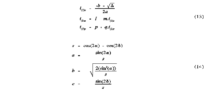
a is the semi-vertex angle of the sphere from the perspective of the origin. is the angle between the vector to the centre of the sphere and the vector to G. The ellipse coefficients a, b and c are the semi-major and semi-minor axes and the shift of the ellipse centre from G along the x axis, respectively. See Figures 2 and 3 for further illustration.
The solid angle integrand
The following equations represent the integrand over which the integration is performed and are equivalent to the condensed equation 4.
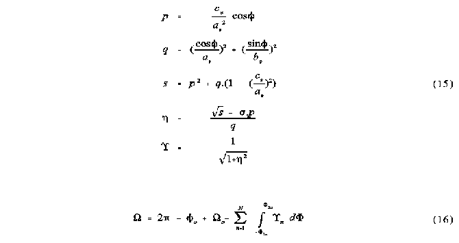
is the parameter integrated.
The total solid angle
The total solid angle for a particular multiple overlap region is calculated according to the following equation, which takes into account the possibility of one of the atoms being centred at G, as would occur, for example, in the case described in figure 6b.
o is the single atom solid angle of the atom centred at G, if any, where o is its angular contribution to the region. n is the result of the integration performed for each ellipse section. The sum is therefore done over all ellipse sections contributing to the region, except for the atom centred at G if there is one. Equation 16 is equivalent to equation 5, but modified to take into account the simpler calculation of the solid angle of the atom centred at G.